microchip公司的MCP2517FD是成本效益和小占位尺寸的CAN FD(灵活数据速率)控制器,具有和微处理器(MCU)接口的SPI接口.器件支持经典格式(CAN2.0B)和CAN灵活数据速率(CAN FD)格式的CAN成帧,比特速率高达1Mbps,工作电压2.7-5.5V,主要用在新能源和智能汽车电子.本文介绍了MCP2517FD主要特性,框图,以及MCP251XFD CAN FD主板主要特性,电路图,材料清单和PCB设计图以及点击板电路图和PCB设计图.
The MCP2517FD is a cost-effective andsmall-footprint CAN FD controller that can be easilyadded to a microcontroller with an available SPIinterface. Therefore, a CAN FD channel can be easilyadded to a microcontroller that is either lacking a CANFD peripheral, or that doesn’t have enough CAN FDchannels.
The MCP2517FD supports both, CAN frames in theClassical format (CAN2.0B) and CAN Flexible DataRate (CAN FD) format, as specified in ISO11898-1:2015.
MCP2517FD主要特性:
General
• External CAN FD Controller with SPI Interface
• Arbitration Bit Rate up to 1 Mbps
• Data Bit Rate up to 8 Mbps
• CAN FD Controller modes
- Mixed CAN 2.0B and CAN FD mode
- CAN 2.0B mode
• Conforms to ISO11898-1:2015
Message FIFOs
• 31 FIFOs, configurable as transmit or receiveFIFOs
• One Transmit Queue (TXQ)
• Transmit Event FIFO (TEF) with 32 bit time stamp
Message Transmission
• Message transmission prioritization:
- Based on priority bit field, and/or
- Message with lowest ID gets transmitted firstusing the Transmit Queue (TXQ)
• Programmable automatic retransmissionattempts: unlimited, 3 attempts or disabled
Message Reception
• 32 Flexible Filter and Mask Objects
• Each object can be configured to filter either:
- Standard ID + first 18 data bits, or
- Extended ID
• 32-bit Time Stamp
Special Features
• VDD: 2.7 to 5.5V
• Active current: max. 12 mA @5.5 V,40 MHz CANclock
• Sleep current: 10 μA, typical
• Message objects are located in RAM: 2 KB
• Up to 3 configurable interrupt pins
• Bus Health Diagnostics and Error counters
• Transceiver standby control
• Start of frame pin for indicating the beginning ofmessages on the bus
• Temperature ranges:
- High (H): C40℃ to +150℃
Oscillator Options
• 40, 20 or 4 MHz crystal, or ceramic resonator; orexternal clock input
• Clock output with prescaler
SPI Interface
• Up to 20 MHz SPI clock speed
• Supports SPI modes 0,0 and 1,1
• Registers and bit fields are arranged in a way toenable efficient access via SPI
Safety Critical Systems
• SPI commands with CRC to detect noise on SPIinterface
• Error Correction Code (ECC) protected RAM
Additional Features
• GPIO pins: INT0 and INT1 can be configured asgeneral purpose I/O
• Open drain outputs: TXCAN, INT, INT0, and INT1pins can be configured as push/pull or open drainoutputs

图1.MCP2517FD框图

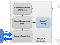
图2.CAN FD控制器模块框图
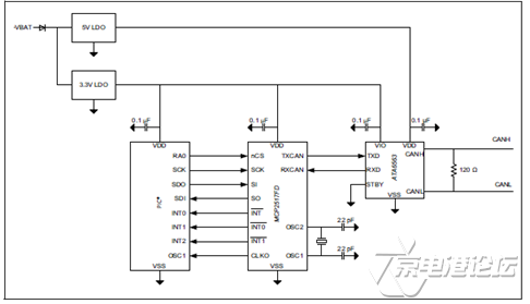
图3. MCP2517FD和3.3V MCU接口电路
MCP251XFD CAN FD主板
The MCP251XFD CAN FD Motherboard provides a simple, low-cost board to evaluate the MCP2517FD family of devices. The board features one mikroBUS™ socket to accommodate the MCP2517FD click Board.
The MCP251XFD CAN FD Motherboard together with the MCP2517FD click Board can be used to implement a CAN FD node.
The MCP251XFD CAN FD Motherboard contains a PIC32MX470F512Hmicrocontroller with a Service Provider Interface (SPI) peripheral. The microcontrollercontrols the MCP2517FD via the SPI interface.
A firmware Application Program Interface (API) is available for rapid applicationdevelopment, which is written in C programming language for MPLAB HarmonyIntegrated Software Framework. It can be easily ported to other microcontrollers.
MCP251XFD CAN FD主板主要特性:
1. PIC32MX470F512H microcontroller
2. mikroBUS socket
3. Debug headers for monitoring the MCP2517FD I/O
4. DSC1121 8 MHz MEMS Clock Generator
5. USB connector to supply regulated +5V DC to the LDO and mikroBUS socket
6. Test loops to supply regulated +5V DC to the LDO and mikroBUS socket
7. Jumper to select between USB and test loop power source
8. 3.3V LDO to supply microcontroller and mikroBUS socket, and power indicatorLEDs
9. Push button switches for user-defined inputs
10. Eight indicator LEDs
11. Microcontroller Reset push button
12. Six-pin interface for the PICkit™ 3 Programmer/Debugger
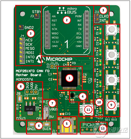
图4.MCP251XFD CAN FD主板外形图
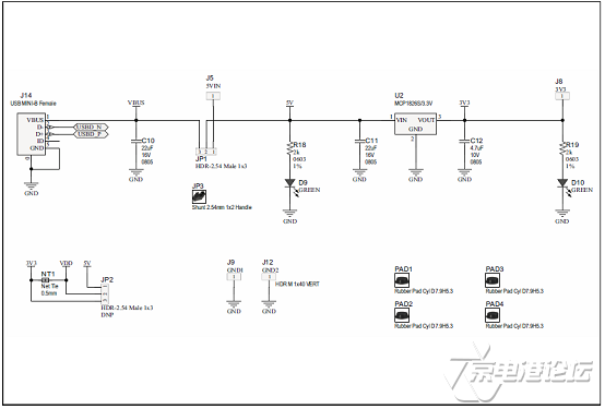
图5.MCP251XFD CAN FD主板电路图(1):电源
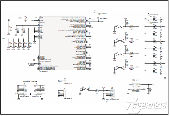
图6.MCP251XFD CAN FD主板电路图(2):MCU
MCP251XFD CAN FD主板材料清单:
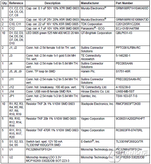


图7.MCP251XFD CAN FD主板PCB正面布局图

图8.MCP251XFD CAN FD主板PCB背面布局图
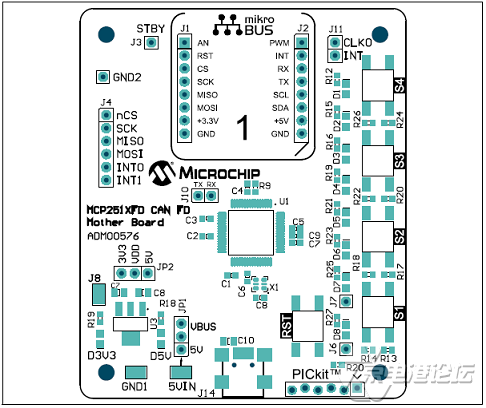
图9.MCP251XFD CAN FD主板PCB正面元件布局图

图10.MCP251XFD CAN FD主板PCB背面元件布局图

图11.MCP251XFD CAN FD主板PCB设计图(1)
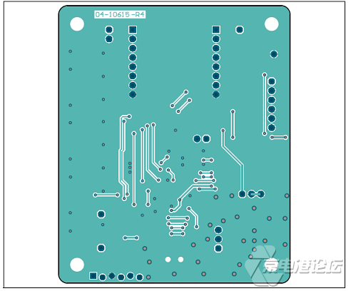
图12.MCP251XFD CAN FD主板PCB设计图(2)
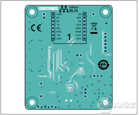
图13.MCP251XFD CAN FD主板PCB设计图(3)
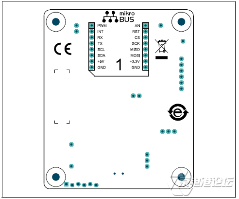
图14.MCP251XFD CAN FD主板PCB设计图(4)

图14.MCP251XFD点击板电路图
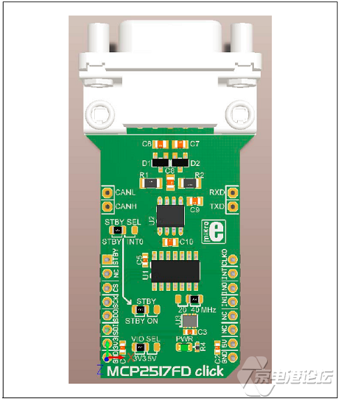
图15.MCP251XFD点击板外形图(正面)

图16.MCP251XFD点击板外形图(背面)
详情请见:
http://ww1.microchip.com/downloads/en/DeviceDoc/20005688A.pdf
和http://ww1.microchip.com/downloads/en/DeviceDoc/50002556A.pdf
以及http://ww1.microchip.com/downloads/en/DeviceDoc/03-10615-R4.PDF
和http://ww1.microchip.com/downloads/en/DeviceDoc/02-10615-R4_BOM_Web.pdf
![]()


 热点图文
热点图文