|
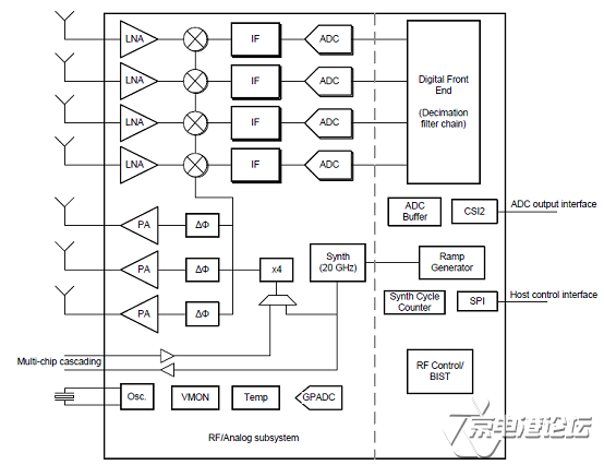
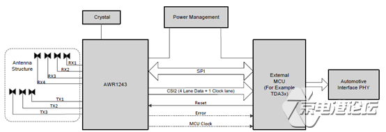
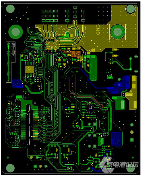
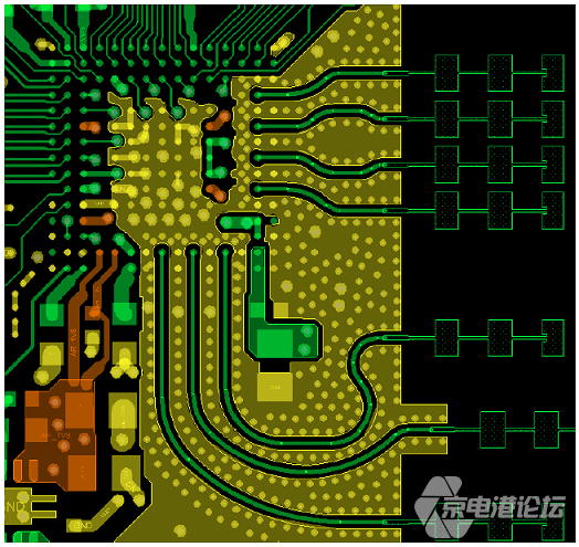
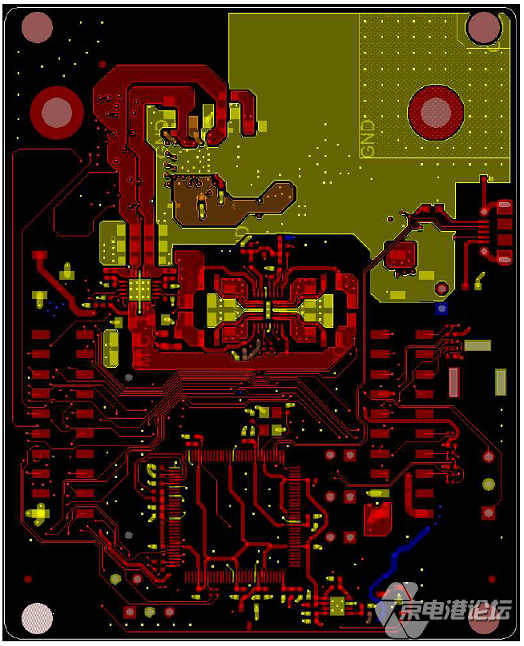
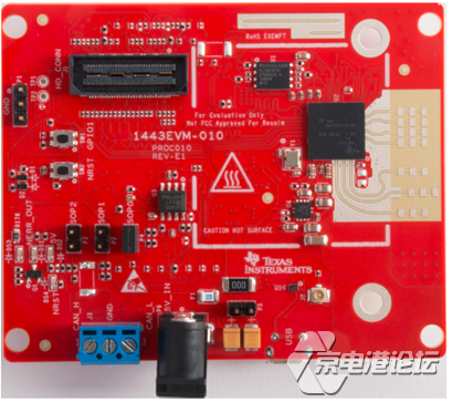
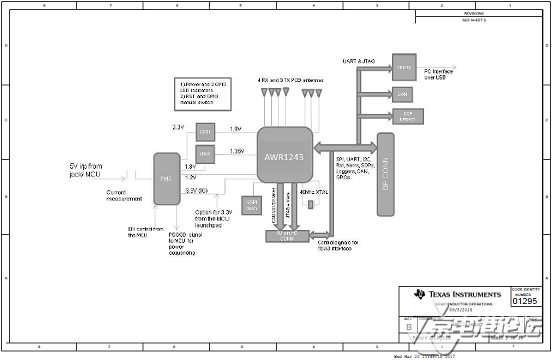
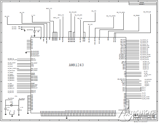
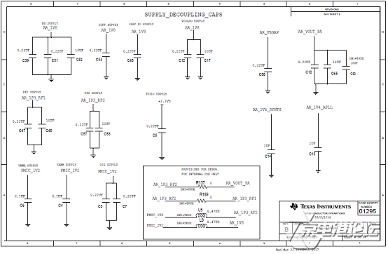
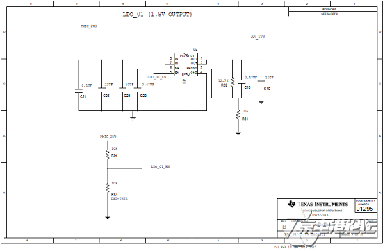
TI公司的AWR1243是单片77GHz和79GHz频率调制连续波(FMCW)收发器,具有基于分数N PLL的超精密啁啾引擎,简化了汽车雷达传感器在76-81GHz的实现方案.采用低功耗45nm RFCMOS工艺,单片实现了内置PLL和A2D转换器的3TX,4RX系统.TX发送功率12dBm,RX噪音15dB (76-77GHz), 16dB(77-81GHz),1MHz时的相位噪音C94 dBc/Hz (76-77 GHz),C91 dBc/Hz (77 - 81 GHz),内置了校准和自测试等功能.主要用在自动高速公路驾驶,自动紧急刹车和自适应巡航控制.本文介绍了AWR1243主要特性,功能框图,短中远距离雷达框图,参考电路,以及AWR1443 BoosterPack™评估板主要特性,框图,电路图,材料清单和PCB设计图. The AWR1243 device is an integrated single-chip FMCW transceiver capable of operation in the 76- to 81-GHz band. The device enables unprecedented levels of integration in an extremely small form factor. AWR1243 is an ideal solution for low power, self-monitored, ultra-accurate radar systems in the automotive space. The AWR1243 device is a self-contained FMCW transceiver single-chip solution that simplifies the implementation of Automotive Radar sensors in the band of 76 to 81 GHz. It is built on TI’s low-power 45-nm RFCMOS process, which enables a monolithic implementation of a 3TX, 4RX system with built-in PLL and A2D converters. Simple programming model changes can enable a wide variety of sensor implementation (Short, Mid, Long) with the possibility of dynamic reconfiguration for implementing a multimode sensor. Additionally, the device is provided as a complete platform solution including reference hardware design, software drivers, sample configurations, API guide, and user documentation. AWR1243主要特性: FMCW Transceiver AWR1243应用: • Automated Highway Driving AWR1443 BoosterPack™评估板 The AWR1443 BoosterPack™ is an easy-to-use evaluation board for the single-chip AWR1443 mmWavesensing device from TI, with direct connectivity to the TI MCU LaunchPad™ ecosystem. The evaluationboard contains everything needed to start developing on a low-power ARM®-R4F controller. Theevaluation board includes onboard emulation for programming and debugging, onboard buttons, andLEDs, for quick integration of a simple user interface. The standard 20-pin BoosterPack headers make the evaluation board compatible with a wide variety of TI MCU LaunchPads and enables easy prototyping. The AWR1243 BoosterPack is an evaluation board for the AWR1243 mmWave high-performance frontend. The evaluation platform enables raw capture of ADC data from the front end and evaluation of RFperformance. AWR1443 BoosterPack™评估板主要特性: • 40-pin LaunchPad standard that leverages the LaunchPad ecosystem AWR1443 BoosterPack™评估板包括: • AWR1443BOOST or AWR1243BOOST 
联系我们我们在此为您提供便利。 今天我们有什么能帮到您的? 全国客服热线 :400 010 6659电话: (北京) 010-80843596 | (北京) 010-82670138 注:如需要相应技能支持,请发电邮yeguozhou@cnecport.com告示您的详细需求。  关注京电港论坛 锁定最新课程活动及技术直播 声明:京电港论坛转载作品均尽可能注明出处,该作品所有人的一切权利均不因本站而转移。 作者如不同意转载,既请通知本站予以删除或改正。转载的作品可能在标题或内容上或许有所改动。 |


 热点图文
热点图文