infineon公司的XMC1400是基于ARM Cortex-M0处理器核的32位MCU,48 MHz时的性能为0.84 DMIPS/MHz (Dhrystone 2.1),具有嵌套矢量中断控制器和64个中断节点以及MATH协处理器,集成了8KB ROM,16KB SRAM和多达200KB 带ECC的闪存以及多种外设,主要用在马达控制和数字电源转换,LED照明和人机接口(HMI).本文先容了XMC1400主要特点,框架图,评估板XMC1400 Boot Kit主要特点,框架图,电路图,质料清单和PCB元件结构图.
The XMC1400 devices are members of the XMC1000 family of microcontrollers basedon the ARM Cortex-M0 processor core. The XMC1400 series addresses the real-timecontrol needs of motor control and digital power conversion. It also features peripheralsfor LED Lighting applications and Human-Machine Interface (HMI).
XMC1400主要特点:
CPU subsystem
• 32-bit ARM Cortex-M0 CPU Core
C 0.84 DMIPS/MHz (Dhrystone 2.1) at48 MHz
• Nested Vectored Interrupt Controller
• 64 interrupt nodes
• MATH coprocessor
C 24-bit trigonometric calculation(CORDIC)
C 32-bit divide operation
• 2x4 channels ERU for eventinterconnections
On-Chip Memories
• 8 Kbyte ROM
• 16 Kbyte SRAM (with parity)
• up to 200 Kbyte Flash (with ECC)
Supply, Reset and Clock
• 1.8 V to 5.5 V supply with power on resetand brownout detector
• On-chip clock monitor
• External crystal oscillator support (32 kHzand 4 to 20 MHz)
• Internal slow and fast oscillators withoutthe need of PLL
System Control
• Window watchdog
• Real time clock module
• Pseudo random number generator
Communication Peripherals
• Two USIC, usable as
C UART (up to 12 Mb/s)
C double-SPI, quad SPI(up to 12 Mb/s)
C IIC (up to 400 kb/s)
C IIS (up to 12 Mb/s)
C LIN interfaces (20kb/s)
• LEDTS in Human-Machine interface
C up to 24 touch pads
C drive up to 144 LEDs
• MultiCAN+, Full-CAN/Basic-CAN with 2nodes, 32 message objects (up to1 MBaud)
Analog Frontend Peripherals
• A/D Converters (up to 12 analog inputs)
C 2 sample and hold stages
C fast 12-bit ADC (up to 1.1 MS/s),adjustable gain
C 0 V to 5.5 V input range
• Up to 8 channels out of rangecomparators
• Up to 4 fast analog comparators
• Temperature Sensor
Industrial Control Peripherals
• 2x4 16-bit 96 MHz CCU4 timers for signalmonitoring and PWM
• 2x4 16-bit 96 MHz CCU8 timers forcomplex PWM, complementary high/lowside switches and multi phase control
• 2x POSIF for hall and quadratureencoders, motor positioning
• 9 channel BCCU (brightness and colorcontrol) for LED lighting applications
Up to 56 Input/Output Ports
• 1.8 V to 5.5 V capable
• up to 8 high current pads (50 mA sink)
On-Chip Debug Support
• 4 breakpoints, 2 watchpoints
• ARM serial wire debug, single-pin debuginterfaces
Programming Support
• Single-pin bootloader
• Secure bootstrap loader SBSL (optional)
Packages
• VQFN40/48/64 (5x5/7x7/8x8mm2)
• LQFP64 (12x12mm2)
Tools
• Free DAVE™ toolchain with lowlevel drivers and apps
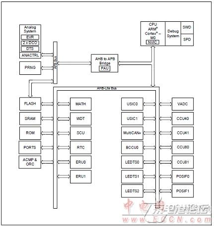
图1.XMC1400框架图
评估板XMC1400 Boot
This document describes the features and hardware details of the XMC1400 Boot Kit. This board is mountedwith ARM® Cortex®-M0 based XMC1400 Microcontroller fromInfineon Technologies AG. This board is part ofInfineon’s XMC1000 Application Kits.
The XMC1400 Boot Kit (CPU-14A-V1) houses the XMC1400 Microcontroller and a 2x30 pin edge for applicationexpansion. The board along with application cards (e.g. Colour LED Card, White LED Card) demonstrates thecapabilities of XMC1400. The main use case for this board is to demonstrate the generic features of XMC1400device, including tool chain. The focus is safe operation under evaluation conditions. The board is neither costnor size optimized and does not serve as a reference design.
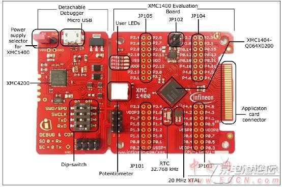
图2.评估板XMC1400 Boot外形图
评估板XMC1400 Boot主要特点:
• XMC1400 (ARM®Cortex®-M0 based) Microcontroller, VQFN64
• Connection to application cards via card edge connector
• Detachable J-Link debugger and UART virtual COM port, withmicro USB connector
• Four user LEDs
• Potentiometer, connected to analog input P2.5
• Power supply via Micro-USB connector
• Usage of 20MHz external crystal for CAN communication
• Usage of 32.768 kHz external crystal as standby clock

图3.评估板XMC1400 Boot框架图
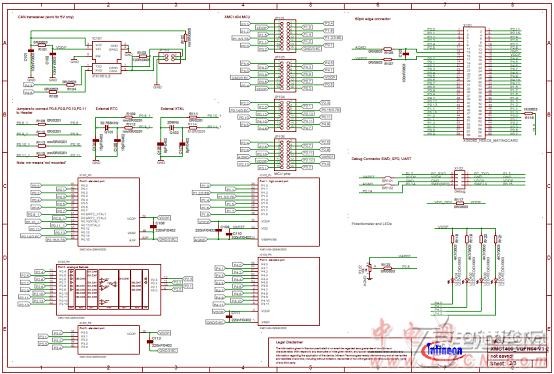
图4.评估板XMC1400 Boot电路图(1)
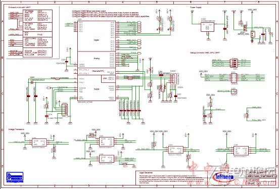
图5.评估板XMC1400 Boot电路图(2)
评估板XMC1400 Boot质料清单:
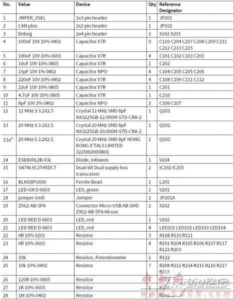


图6.评估板XMC1400 Boot PCB结构图
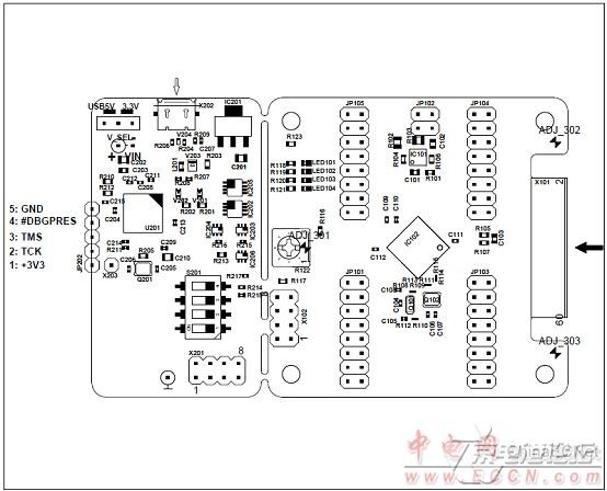
图7.评估板XMC1400 Boot PCB元件结构图
详情请复制打开此衔接地址:
http://www.infineon.com/dgdl/Infineon-XMC1400-DS-v00_30-EN.pdf?fileId=5546d46250cc1fdf015110a2596343b2
和http://www.infineon.com/dgdl/Infineon-Board_Users_Manual_XMC1400_Boot_Kit.pdf-UM-v01_00-EN.pdf?fileId=5546d462525dbac401527815f9a073fd
 Infineon-XMC1400-DS-v00_30-EN.pdf
Infineon-Board_Users_Manual_XMC1400_Boot_Kit.pdf-UM-v01_00-EN.pdf


 热点图文
热点图文