|
TI公司的AM3359是{方案}ARM Cortex-A8处理器的微处理器,具有增强的图像图形处理以及外设和工业接口选择如EtherCAT和PROFIBUS,器件支持高级利用系统(HLOS).工作频率高达1GHz,NEON™ SIMD协处理器,集成了32KB L1指令和32KB数据缓存,带误差修正码(ECC)的256KB L2缓存,176KB引导ROM,64KB专用RAM以及中断控制器.主要用在游戏外设,家庭和工业自动化,消费类医疗电器,打印机,智能玩具系统,毗连的售货机和称重仪.本京电港论坛文章先容了AM3359主要功能特点和功能框架原理图,以及用于变电站自动化的并行冗余协议(PRP)以太网参考方案TIDEP0054主要特点,框架图,电路原理图纸,质料清单和PCB线路板线路板设计原理图.
The AM335x microprocessors, based on the ARM Cortex-A8 processor, are enhanced with image,graphics processing, peripherals and industrial interface options such as EtherCAT and PROFIBUS. Thedevices support high-level operating systems (HLOS). Linux® and Android™ are available free of chargefrom TI.
The AM335x microprocessor contain the subsystems sand a brief description of each follows:
The microprocessor unit (MPU) subsystem is based on the ARM Cortex-A8 processor and the PowerVRSGX™ Graphics Accelerator subsystem provides 3D graphics acceleration to support display and gamingeffects.
The PRU-ICSS is separate from the ARM core, allowing independent operation and clocking for greaterefficiency and flexibility. The PRU-ICSS enables additional peripheral interfaces and real-time protocolssuch as EtherCAT, PROFINET, EtherNet/IP, PROFIBUS, Ethernet Powerlink, Sercos, and others.
Additionally, the programmable nature of the PRU-ICSS, along with its access to pins, events and allsystem-on-chip (SoC) resources, provides flexibility in implementing fast, real-time responses, specializeddata handling operations, custom peripheral interfaces, and in offloading tasks from the other processorcores of SoC.
AM3359主要特点:
• Up to 1-GHz Sitara™ ARM® Cortex®-A8 32‑BitRISC Processor
C NEON™ SIMD Coprocessor
C 32KB of L1 Instruction and 32KB of Data CacheWith Single-Error Detection (Parity)
C 256KB of L2 Cache With Error Correcting Code(ECC)
C 176KB of On-Chip Boot ROM
C 64KB of Dedicated RAM
C Emulation and Debug - JTAG
C Interrupt Controller (up to 128 InterruptRequests)
• On-Chip Memory (Shared L3 RAM)
C 64KB of General-Purpose On-Chip MemoryController (OCMC) RAM
C Accessible to All Masters
C Supports Retention for Fast Wakeup
• External Memory Interfaces (EMIF)
C mDDR(LPDDR), DDR2, DDR3, DDR3LController:
• mDDR: 200-MHz Clock (400-MHz DataRate)
• DDR2: 266-MHz Clock (532-MHz Data Rate)
• DDR3: 400-MHz Clock (800-MHz Data Rate)
• DDR3L: 400-MHz Clock (800-MHz DataRate)
• 16-Bit Data Bus
• 1GB of Total Addressable Space
• Supports One x16 or Two x8 Memory DeviceConfigurations
C General-Purpose Memory Controller (GPMC)
• Flexible 8-Bit and 16-Bit AsynchronousMemory Interface With up to Seven ChipSelects (NAND, NOR, Muxed-NOR, SRAM)
• Uses BCH Code to Support 4-, 8-, or 16-BitECC
• Uses Hamming Code to Support 1-Bit ECC
C Error Locator Module (ELM)
• Used in Conjunction With the GPMC toLocate Addresses of Data Errors fromSyndrome Polynomials Generated Using aBCH Algorithm
• Supports 4-, 8-, and 16-Bit per 512-ByteBlock Error Location Based on BCHAlgorithms
• Programmable Real-Time Unit Subsystem andIndustrial Communication Subsystem (PRU-ICSS)
C Supports Protocols such as EtherCAT®,PROFIBUS, PROFINET, EtherNet/IP™, and
More
C Two Programmable Real-Time Units (PRUs)
• 32-Bit Load/Store RISC Processor Capableof Running at 200 MHz
• 8KB of Instruction RAM With Single-ErrorDetection (Parity)
• 8KB of Data RAM With Single-ErrorDetection (Parity)
• Single-Cycle 32-Bit Multiplier With 64-BitAccumulator
• Enhanced GPIO Module Provides Shift-In/Out Support and Parallel Latch onExternal Signal
C 12KB of Shared RAM With Single-ErrorDetection (Parity)
C Three 120-Byte Register Banks Accessible byEach PRU
C Interrupt Controller (INTC) for Handling SystemInput Events
C Local Interconnect Bus for Connecting Internaland External Masters to the Resources Insidethe PRU-ICSS
C Peripherals Inside the PRU-ICSS:
• One UART Port With Flow Control Pins,Supports up to 12 Mbps
• One Enhanced Capture (eCAP) Module
• Two MII Ethernet Ports that SupportIndustrial Ethernet, such as EtherCAT
• One MDIO Port
• Power, Reset, and Clock Management (PRCM)Module
C Controls the Entry and Exit of Stand-By andDeep-Sleep Modes
C Responsible for Sleep Sequencing, PowerDomain Switch-Off Sequencing, Wake-Up
Sequencing, and Power Domain Switch-OnSequencing
C Clocks
• Integrated 15- to 35-MHz High-FrequencyOscillator Used to Generate a Reference
Clock for Various System and PeripheralClocks
• Supports Individual Clock Enable andDisable Control for Subsystems andPeripherals to Facilitate Reduced PowerConsumption
• Five ADPLLs to Generate System Clocks(MPU Subsystem, DDR Interface, USB and
Peripherals [MMC and SD, UART, SPI, I2C],L3, L4, Ethernet, GFX [SGX530], LCD Pixel
Clock)
C Power
• Two Nonswitchable Power Domains (Real-Time Clock [RTC], Wake-Up Logic[WAKEUP])
• Three Switchable Power Domains (MPUSubsystem [MPU], SGX530 [GFX],Peripherals and Infrastructure [PER])
• Implements SmartReflex™ Class 2B forCore Voltage Scaling Based On DieTemperature, Process Variation, andPerformance (Adaptive Voltage Scaling[AVS])
• Dynamic Voltage Frequency Scaling (DVFS)
• Real-Time Clock (RTC)
C Real-Time Date (Day-Month-Year-Day of Week)and Time (Hours-Minutes-Seconds) Information
C Internal 32.768-kHz Oscillator, RTC Logic and1.1-V Internal LDO
C Independent Power-on-Reset(RTC_PWRONRSTn) Input
C Dedicated Input Pin (EXT_WAKEUP) forExternal Wake Events
C Programmable Alarm Can be Used to GenerateInternal Interrupts to the PRCM (for Wakeup) orCortex-A8 (for Event Notification)
C Programmable Alarm Can be Used WithExternal Output (PMIC_POWER_EN) to Enablethe Power Management IC to Restore Non-RTCPower Domains
• Peripherals
C Up to Two USB 2.0 High-Speed OTG PortsWith Integrated PHY
C Up to Two Industrial Gigabit Ethernet MACs (10,100, 1000 Mbps)
• Integrated Switch
• Each MAC Supports MII, RMII, RGMII, andMDIO Interfaces
• Ethernet MACs and Switch Can OperateIndependent of Other Functions
• IEEE 1588v2 Precision Time Protocol (PTP)
C Up to Two Controller-Area Network (CAN) Ports
• Supports CAN Version 2 Parts A and B
C Up to Two Multichannel Audio Serial Ports(McASPs)
• Transmit and Receive Clocks up to 50 MHz
• Up to Four Serial Data Pins per McASP PortWith Independent TX and RX Clocks
• Supports Time Division Multiplexing (TDM),Inter-IC Sound (I2S), and Similar Formats
• Supports Digital Audio Interface
Transmission (SPDIF, IEC60958-1, andAES-3 Formats)
• FIFO Buffers for Transmit and Receive (256Bytes)
C Up to Six UARTs
• All UARTs Support IrDA and CIR Modes
• All UARTs Support RTS and CTS FlowControl
• UART1 Supports Full Modem Control
C Up to Two Master and Slave McSPI SerialInterfaces
• Up to Two Chip Selects
• Up to 48 MHz
C Up to Three MMC, SD, SDIO Ports
• 1-, 4- and 8-Bit MMC, SD, SDIO Modes
• MMCSD0 has Dedicated Power Rail for1.8‑V or 3.3-V Operation
• Up to 48-MHz Data Transfer Rate
• Supports Card Detect and Write Protect
• Complies With MMC4.3, SD, SDIO 2.0Specifications
C Up to Three I2C Master and Slave Interfaces
• Standard Mode (up to 100 kHz)
• Fast Mode (up to 400 kHz)
C Up to Four Banks of General-Purpose I/O(GPIO) Pins
• 32 GPIO Pins per Bank (Multiplexed WithOther Functional Pins)
• GPIO Pins Can be Used as Interrupt Inputs(up to Two Interrupt Inputs per Bank)
C Up to Three External DMA Event Inputs that canAlso be Used as Interrupt Inputs
C Eight 32-Bit General-Purpose Timers
• DMTIMER1 is a 1-ms Timer Used forOperating System (OS) Ticks
• DMTIMER4CDMTIMER7 are Pinned Out
C One Watchdog Timer
C SGX530 3D Graphics Engine
• Tile-Based Architecture Delivering up to 20Million Polygons per Second
• Universal Scalable Shader Engine (USSE) isa Multithreaded Engine Incorporating Pixel
and Vertex Shader Functionality
• Advanced Shader Feature Set in Excess ofMicrosoft VS3.0, PS3.0, and OGL2.0
• Industry Standard API Support of Direct3DMobile, OGL-ES 1.1 and 2.0, OpenVG 1.0,and OpenMax
• Fine-Grained Task Switching, LoadBalancing, and Power Management
• Advanced Geometry DMA-Driven Operationfor Minimum CPU Interaction
• Programmable High-Quality Image Anti-Aliasing
• Fully Virtualized Memory Addressing for OSOperation in a Unified Memory Architecture
C LCD Controller
• Up to 24-Bit Data Output; 8 Bits per Pixel(RGB)
• Resolution up to 2048 × 2048 (WithMaximum 126-MHz Pixel Clock)
• Integrated LCD Interface Display Driver(LIDD) Controller
• Integrated Raster Controller
• Integrated DMA Engine to Pull Data from theExternal Frame Buffer Without Burdening the
Processor via Interrupts or a Firmware Timer
• 512-Word Deep Internal FIFO
• Supported Display Types:
C Character Displays - Uses LIDDController to Program these Displays
C Passive Matrix LCD Displays - Uses LCDRaster Display Controller to ProvideTiming and Data for Constant GraphicsRefresh to a Passive Display
C Active Matrix LCD Displays C UsesExternal Frame Buffer Space and theInternal DMA Engine to Drive StreamingData to the Panel
C 12-Bit Successive Approximation Register(SAR) ADC
• 200K Samples per Second
• Input can be Selected from any of the EightAnalog Inputs Multiplexed Through an 8:1
Analog Switch
• Can be Configured to Operate as a 4-Wire,5-Wire, or 8-Wire Resistive Touch Screen
Controller (TSC) Interface
C Up to Three 32-Bit eCAP Modules
• Configurable as Three Capture Inputs orThree Auxiliary PWM Outputs
C Up to Three Enhanced High-Resolution PWMModules (eHRPWMs)
• Dedicated 16-Bit Time-Base Counter WithTime and Frequency Controls
• Configurable as Six Single-Ended, Six Dual-Edge Symmetric, or Three Dual-Edge
Asymmetric Outputs
C Up to Three 32-Bit Enhanced QuadratureEncoder Pulse (eQEP) Modules
• Device Identification
C Contains Electrical Fuse Farm (FuseFarm) ofWhich Some Bits are Factory Programmable
• Production ID
• Device Part Number (Unique JTAG ID)
• Device Revision (Readable by Host ARM)
• Debug Interface Support
C JTAG and cJTAG for ARM (Cortex-A8 andPRCM), PRU-ICSS Debug
C Supports Device Boundary Scan
C Supports IEEE 1500
• DMA
C On-Chip Enhanced DMA Controller (EDMA) hasThree Third-Party Transfer Controllers (TPTCs)and One Third-Party Channel Controller(TPCC), Which Supports up to 64Programmable Logical Channels and EightQDMA Channels. EDMA is Used for:
• Transfers to and from On-Chip Memories
• Transfers to and from External Storage(EMIF, GPMC, Slave Peripherals)
• Inter-Processor Communication (IPC)
C Integrates Hardware-Based Mailbox for IPC andSpinlock for Process Synchronization BetweenCortex-A8, PRCM, and PRU-ICSS
• Mailbox Registers that Generate Interrupts
C Four Initiators (Cortex-A8, PRCM, PRU0,PRU1)
• Spinlock has 128 Software-Assigned LockRegisters
• Security
C Crypto Hardware Accelerators (AES, SHA,RNG)
C Secure Boot
• Boot Modes
C Boot Mode is Selected Through BootConfiguration Pins Latched on the Rising Edgeof the PWRONRSTn Reset Input Pin
• Packages:
C 298-Pin S-PBGA-N298 Via Channel Package(ZCE Suffix), 0.65-mm Ball Pitch
C 324-Pin S-PBGA-N324 Package(ZCZ Suffix), 0.80-mm Ball Pitch
AM3359应用:
• Gaming Peripherals
• Home and Industrial Automation
• Consumer Medical Appliances
• Printers
• Smart Toll Systems
• Connected Vending Machines
• Weighing Scales
• Educational Consoles
• Advanced Toys
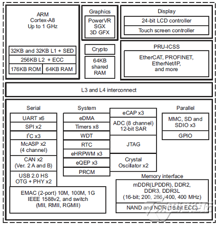
图1{京电港论坛}{京电港论坛}. AM3359框架图
用于变电站自动化的并行冗余协议(PRP)以太网参考方案
This TI Design is a solution for high reliability,low-latency network communications for substation-automation equipment in smart gridtransmission and distribution networks. It supports theParallel Redundancy Protocol (PRP) specification inthe IEC 62439 standard. This solution is a lower-costalternative to FPGA approaches and provides theflexibility and performance to add features such asIEC 61850 support without additional components.
A substation is a key component of the electricity-grid infrastructure, located everywhere from powergeneration facilities throughout the distribution network to the low-voltage feeders serving residences andbusinesses. Substations are a primary factor in transforming voltage levels for transmission andperforming important functions such as switching, monitoring, and protecting sub-systems in order tomaintain grid efficiency and reliability. Traditional-substation systems focused on fault monitoring that canbe manually fixed by switching to backup subsystems.
Consumers, regulators, and grid operators demand increasing reliability of electricity delivery. Theintroduction of automatic switching and protection of subsystems increases the demand for the automationof substation operations and communications to monitor grid conditions and communicate information togrid operators.
Operators need to continually monitor the health of networks and take action to maintain the operationwith efficiency. This need leads to the requirement for reliable and low-latency communications betweenthe control center of the operator and high-value nodes such as substations.
The International Electro-Technical Commission (IEC) released specifications for industrial-Ethernetcommunications under the IEC 62439 standard. The PRP specification is one of the IEC 62439-3standards that provides a static redundancy Ethernet-based protocol that supports critical real-timesystems that require continuous monitoring.
并行冗余协议(PRP)以太网参考方案主要特点:
• Compliant to IEC 62439-3 Clause 4 Specificationfor PRP-Ethernet Communications
• Traffic Filtering Based on Virtual Local-AreaNetwork (VLAN) IDs, Multicast and Broadcast
Support, and Built-in Storm Prevention andSupervision Mechanism
• Zero Recovery Time in Case of Network Failure
• Dual-Ported Full-Duplex 100-Mbps Ethernet
• Fully Programmable Solution Provides Platform forIntegration of Additional Applications
并行冗余协议(PRP)以太网参考方案特点应用:
• Substation and Distribution Automation
• Protection Relays
• Smart-Grid Communication
• Factory Automation

图2{京电港论坛}{京电港论坛}.并行冗余协议(PRP)以太网参考方案外形实物图

图3{京电港论坛}{京电港论坛}.并行冗余协议(PRP)以太网参考方案框架图
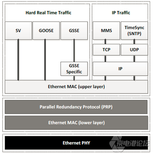
图4{京电港论坛}{京电港论坛}.并行冗余协议(PRP)以太网参考方案系统架构图
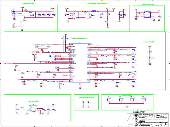
图5{京电港论坛}{京电港论坛}.并行冗余协议(PRP)以太网参考方案电路原理图纸(1)

图6{京电港论坛}{京电港论坛}.并行冗余协议(PRP)以太网参考方案电路原理图纸(2)
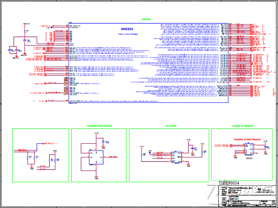
图7{京电港论坛}{京电港论坛}.并行冗余协议(PRP)以太网参考方案电路原理图纸(3)

图8{京电港论坛}{京电港论坛}.并行冗余协议(PRP)以太网参考方案电路原理图纸(4)
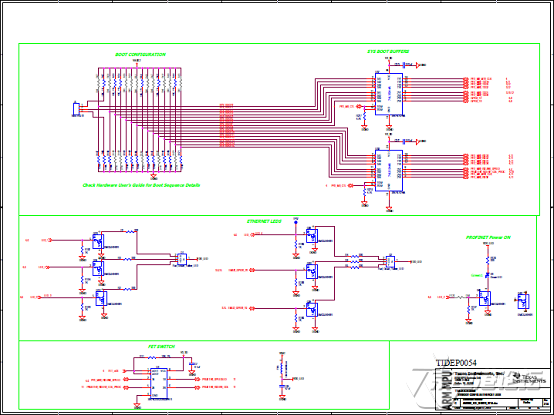
图9{京电港论坛}{京电港论坛}.并行冗余协议(PRP)以太网参考方案电路原理图纸(5)

图1{京电港论坛}0.并行冗余协议(PRP)以太网参考方案电路原理图纸(6)
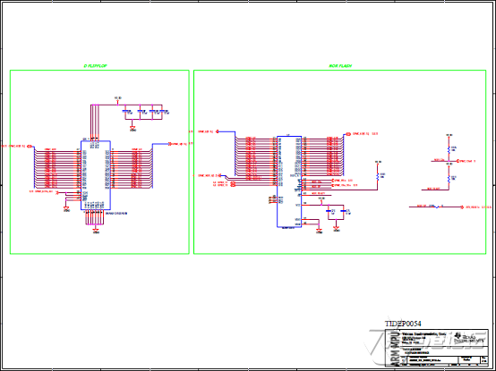
图1{京电港论坛}1.并行冗余协议(PRP)以太网参考方案电路原理图纸(7)
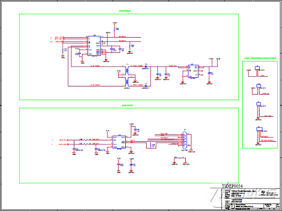
图1{京电港论坛}2.并行冗余协议(PRP)以太网参考方案电路原理图纸(8)
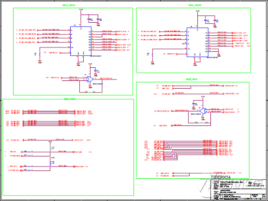
图1{京电港论坛}3.并行冗余协议(PRP)以太网参考方案电路原理图纸(9)

图1{京电港论坛}4.并行冗余协议(PRP)以太网参考方案电路原理图纸(10)
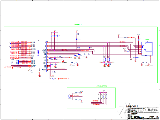
图1{京电港论坛}5.并行冗余协议(PRP)以太网参考方案电路原理图纸(11)
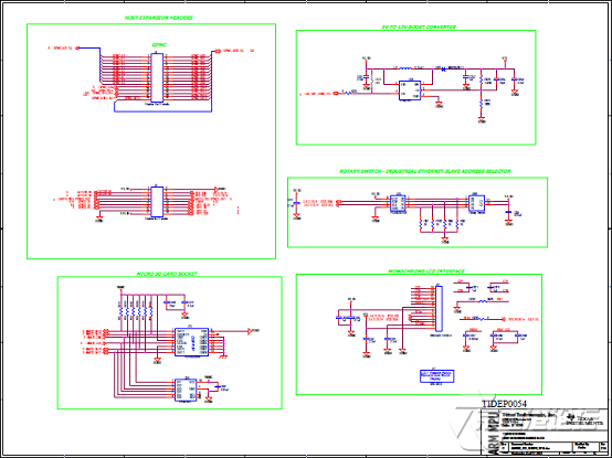
图1{京电港论坛}6.并行冗余协议(PRP)以太网参考方案电路原理图纸(12)

图1{京电港论坛}7.并行冗余协议(PRP)以太网参考方案电路原理图纸(13)
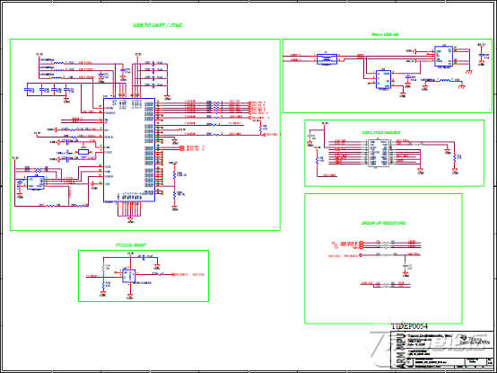
图1{京电港论坛}8.并行冗余协议(PRP)以太网参考方案电路原理图纸(14)
并行冗余协议(PRP)以太网参考方案质料清单:

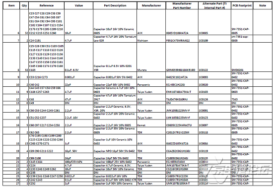
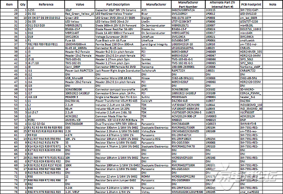

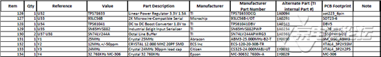

图1{京电港论坛}9.并行冗余协议(PRP)以太网参考方案PCB线路板设计原理图(1)
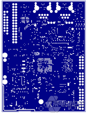
图2{京电港论坛}0.并行冗余协议(PRP)以太网参考方案PCB线路板设计原理图(2)

图2{京电港论坛}1.并行冗余协议(PRP)以太网参考方案PCB线路板设计原理图(3)

图2{京电港论坛}2.并行冗余协议(PRP)以太网参考方案PCB线路板设计原理图(4)

图2{京电港论坛}3.并行冗余协议(PRP)以太网参考方案PCB线路板设计原理图(5)
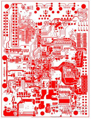
图2{京电港论坛}4.并行冗余协议(PRP)以太网参考方案PCB线路板设计原理图(6)
详情请复制打开此衔接所在:
http://www.ti.com/lit/ds/symlink/am3359.pdf
和http://www.ti.com/lit/ug/tidubn6/tidubn6.pdf
以及http://www.ti.com/seclit/df/tidrln1/tidrln1.pdf
和http://www.ti.com/seclit/df/tidrln2/tidrln2.pdf
与http://www.ti.com/seclit/df/tidrln4/tidrln4.pdf
 am3359.pdf am3359.pdf
tidrln1.pdf
tidrln2.pdf
tidrln4.pdf
tidubn6.pdf 声明:本网站原创内容,如需转载,请注明出处;本网站转载的内容(文章、图片、视频)等资料版权归原网站所有。如昨们采取了您不宜公开的文章或图片,未能实时和您确认,制止给双方造成不须要的经济损失,请电邮接洽昨们,以便迅速接纳适当处理步调;接待投稿,邮箱:editors@eccn.com。 [上一篇:] [方案] ADI ADAQ7980 16位模数转换器(ADC)子系统开发方案 [下一篇:] [方案] Microchip MCP19215双路电源PWM控制方案 猜你喜欢
- 瑞萨电子推出增强型RX65N/RX651微控制器,强化工业物联网的安全性
- 瑞萨电子推出新型超低功耗微控制器,对带LED和LCD显示屏的电容式触摸按键应用举行优化
- 研华x86/ARM多平台方案 助力KIOSK快速落地
- 研华发布多毗连IoT网关UTX-3117 ,物联网应用如虎添翼
- 设立香港馆推广香港线路板制造商
- 宜鼎发布iCAP大规模存储系统管理方案 引领云端存储管理新趋势
- 壹秘和XMOS宣布结成相助同伴关系,使壹秘AI聚会集会助手具备领先远场语音技能
- 再获国际奖项! 越疆魔术师荣获2018 CES创新大奖
- [方案] Lattice MachXO3LF-9400C PLD系列开辟方案
- [方案] ST STM32H743I高性能400MHz 32位ARM MCU开辟方案
- 大联大诠鼎团体推出{方案}MicroVision的微激光扫描投影技能在医疗范畴的应用方案
- [方案] NXP S32V234视频处理器开辟方案
相关产物 >>更多
- ADI推出两款50 Mbps RS-485/RS-422收发器
- Maxim最新推出除颤脉冲和ESD掩护器件
- ROHM开辟出丈量脉搏信号的脉搏传感器“BH1790GLC”
- Maxim推出超小尺寸hSensor平台
- 雅特生科技推出全新的ASA 6W-M 系列 6W直流/直流电源转换器
- 研华推出头向工业自动化范畴的RISC超低功耗3.5"单板电脑
- 美高森美推出用于工业、安全和医疗应用的极低功耗sub-GHz射频(RF)收发器
- Molex公司Super Sabre电源毗连器系统
相关市场新闻 >>更多
- 红狮PTV安灯管理服务器系统有效提升国内某知名车企生产效率
- 兆易创新GD32 MCU荣获“中国芯”最佳市场体现产物奖
- TUV南德受邀加入2017国际服务呆板人产业发展高峰论坛
- 郑州工博会成为中部地域首个通过UFI认证展会
- 工控系统危机潜伏,安全问题如何面临?
- 红狮RAM工业蜂窝RTU提供市场领先的工业物联网 (IIoT) 毗连
- 直击智能化海潮 专业论坛点亮NEPCON South China 2017
- Sierraware开辟的兼容GlobalPlatform的可信任执行情况(TEE)已支持MIPS-based 设备
最新供应方案 >>更多
- [方案] NXP i.MX 6UltraLitePICO入门板开辟方案
- [方案] Infineon IDP2303120W开关电源(SMPS)参考方案方案
- [方案] Lattice MachXO3LF-9400C PLD系列开辟方案
- [方案] TI TIDA-03027USB Type-C多端口适配器电源参考方案
热门博客 >>更多
- 大联大品佳团体推出{方案}NXP产物并接入fogCloud的智能照明控制管理方案
- 德州仪器首款量产超低功耗双频无线MCU首发问世
- 专访:Navitas(纳薇半导体)CEO Gene Sheridan
- STSPIN电池系列产物以微型、低压、高能效抢占物联网电机驱动市场
英华BBS >>更多
- FREESCALE单片机的C编程
- [履历之谈]9S12的MSCAN速率配置及错误帧故障的办理
- 【求助】XS256 步伐的常量51KB超出non-banked FLASH 后怎么办【迫切】
- 求助mc9s12xep100 bootloader
京电港 中国电子行业研发工程师一站式服务平台 关于京电港| 广告招商| 接洽昨们| 招聘信息| 友情链接| 京电港导航| 手机京电港 |  京电港官方微博 京电港官方微博 Copyright © 2000- 京电港 版权所有 粤ICP备17063136号-2 增值电信业务谋划许可证粤B2-20050142 京公网安备11010802010546号 Tel: 010-51077700, 0755-33322333 Fax: 010-51077511, 0755-33322099 
PageStat: Processed in Memory usage: 41.303734 MB
|


 热点图文
热点图文