infineon公司的XMC4400是基于32位ARM Cortex-M4处理器核的XMC4000系列处理器,工作频率120MHz,具有16位和32位Thumb2指令集和DSP/MAC指令,集成了16KB引导ROM,16KB高速步伐存储器,16KB高速数据存储器,32KB高速通信存储器和带4KB指令缓存的512KB闪存,以及多种外设,主要用在工业毗连,工业控制,电源转换,检测和控制等.本文先容了XMC4400主要特点,系统框架图以及750W三相马达控制板KIT_XMC750WATT_AK_V1主要特点,电路图,质料清单和PCB元件结构图.
The XMC4400 devices are members of the XMC4000 Family of microcontrollers based on the ARM Cortex-M4 processor core. The XMC4000 is a family of high performance and energy efficient microcontrollers optimized for Industrial Connectivity, Industrial Control, Power Conversion, Sense & Control.
XMC4400 combines Infineon’s leading-edge peripheral set with an industry-standard ARM® Cortex™-M4. As one of its key features it offers a high-resolution PWM unit with a tiny resolution of 150ps. This unique peripheral makes it especially suitable for digital power conversion in applications like solar inverters as well as SMPS and uninterruptible power supplies (UPS). Other applications are motor controllers, sense&control and IO devices for factory automation and user interface systems (HMI). XMC4400 is supported by Infineon’s integrated development platform DAVE™ 3, which makes convenient, fast and application-orientated software development possible.
XMC4400主要特点:
ARM® Cortex™-M4, 120MHz, incl. single cycle DSP MAC and floating point unit (FPU)
8-channel DMA + dedicated DMAs for USB and Ethernet
USB 2.0 full-speed on-the-go
CPU Frequency: 120MHz
eFlash:256kB including hardware ECC
80kB SRAM
Package: PG-LQFP-100
CPU Subsystem
• CPU Core
C High Performance 32-bit ARM Cortex-M4 CPU
C 16-bit and 32-bit Thumb2 instruction set
C DSP/MAC instructions
C System timer (SysTick) for Operating System support
• Floating Point Unit
• Memory Protection Unit
• Nested Vectored Interrupt Controller
• One General Purpose DMA with up-to 8 channels
• Event Request Unit (ERU) for programmable processing of external and internalservice requests
• Flexible CRC Engine (FCE) for multiple bit error detection
On-Chip Memories
• 16 KB on-chip boot ROM
• 16 KB on-chip high-speed program memory
• 32 KB on-chip high speed data memory
• 32 KB on-chip high-speed communication memory
• 512 KB on-chip Flash Memory with 4 KB instruction cache
Communication Peripherals
• Ethernet MAC module capable of 10/100 Mbit/s transfer rates
• Universal Serial Bus, USB 2.0 host, Full-Speed OTG, with integrated PHY
• Controller Area Network interface (MultiCAN), Full-CAN/Basic-CAN with two nodes,64 message objects (MO), data rate up to 1MBit/s
• Four Universal Serial Interface Channels (USIC), providing four serial channels,usable as UART, double-SPI, quad-SPI, IIC, IIS and LIN interfaces
• LED and Touch-Sense Controller (LEDTS) for Human-Machine interface
Analog Frontend Peripherals
• Four Analog-Digital Converters (VADC) of 12-bit resolution, 8 channels each, withinput out-of-range comparators
• Delta Sigma Demodulator with four channels, digital input stage for A/D signalconversion
• Digital-Analog Converter (DAC) with two channels of 12-bit resolution
Industrial Control Peripherals
• Two Capture/Compare Units 8 (CCU8) for motor control and power conversion
• Four Capture/Compare Units 4 (CCU4) for use as general purpose timers
• Four High Resoultion PWM (HRPWM) channels
• Two Position Interfaces (POSIF) for servo motor positioning
• Window Watchdog Timer (WDT) for safety sensitive applications
• Die Temperature Sensor (DTS)
• Real Time Clock module with alarm support
• System Control Unit (SCU) for system configuration and control
Input/Output Lines
• Programmable port driver control module (PORTS)
• Individual bit addressability
• Tri-stated in input mode
• Push/pull or open drain output mode
• Boundary scan test support over JTAG interface
On-Chip Debug Support
• Full support for debug features: 8 breakpoints, CoreSight, trace
• Various interfaces: ARM-JTAG, SWD, single wire trace
XMC4400目标应用:
Motor control
Position detection
IO devices
HMI
Solar inverters
SMPS
Sense & control systems
PLC
UPS
Light networks
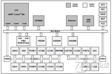
图1.XMC4400系统框架图
750W三相马达控制板KIT_XMC750WATT_AK_V1
XMC 750 Watt Motor Control Application Kit 3-Phase drives evaluation with galvanic isolation
The motor control application kit KIT_XMC750WATT_AK_V1 is designed for use with 230V AC mains power supply. The drive cards provide a galvanically isolated debug interface that allows safe software development.
A PFC circuitry can be controlled by the on-board PFC IC or by the microcontroller at the drive card. The power inverter bridge is built by 6 discrete IGBTs in DPAK package. Each leg provides a shunt resistor with amplifier for phase current measurement. The DC-link also provides a shunt resistor with amplifier for reconstruction of the phase current with single shunt method. An additional low pass filter allows measuring the average DC-link current as well. The power supply for the control devices as well as the drive card is provided by a non isolatedflyback converter which provides 5V and 15V DC. The auxiliary power board connector allows adding an inverter card in order to use the board together with the XMC4400 drive card as dual inverter.
The main use case for this board is to demonstrate the generic features of the XMC microcontroller devices including tool chain. The focus is the operation under evaluation conditions. The board is neither cost nor size optimized and does not serve as a reference design.
750W三相马达控制板KIT_XMC750WATT_AK_V1主要特点:
The XMC Motor Control Appkication Kit (KIT_XMC750WATT_AK_V1) provides the following features:
3 Phase Power Inverter 750W V1.1 (2013/45)
− Power supply with line filter, NTC bypass relay and PFC circuitry
− 3 phase bridge realized with discrete IGBTs (IKD10N60R)
− Integrated gate driver with integrated boot strap diodes and protection features (6EDL04I06NT)
− PFC control via control IC (ICE3PCS02), MCU or disabled
− PFC overcurrent protection fully realized in hardware
− On-board power supply for control components (15V and 5V) with flyback controller (ICE3B0356JG)
− Voltage dividers for DC-link and inverter output voltage measurement (e.g. for motor back EMF detection)
− Current sensing circuitry for
o PFC
o DC-link current (single shunt measurement)
o Low side inverter leg currents (emitter shunt measurement)
− Auxiliary power board connector for optional inverter card
Drive Card XMC1300
− XMC1302 (ARM® Cortex™-M0-based) Microcontroller, 200 kByte on-chip Flash, TSSOP38
− 1 set of combined hall sensor and encoder interfaces
− Potentiometer
− Isolated Debug Interface
Drive Card XMC4400
− XMC4400 (ARM® Cortex™-M4-based) Microcontroller, 512 kByte on-chip Flash, LQFP100
− 2 sets of combined hall sensor and encoder interfaces
− Multi feedback interface connectors for connection of resolver circuitry,UART, SPI, I2C, USB, etc
− Potentiometer
− Isolated Debug Interface
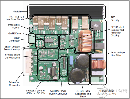
图2.750W三相马达控制板KIT_XMC750WATT_AK_V1外形图
750W三相马达控制板KIT_XMC750WATT_AK_V1主要指标:
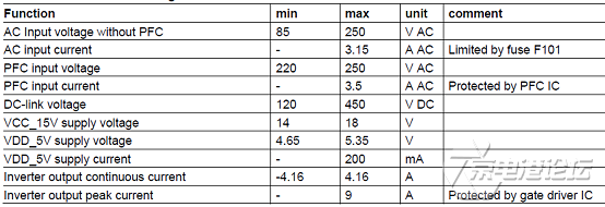
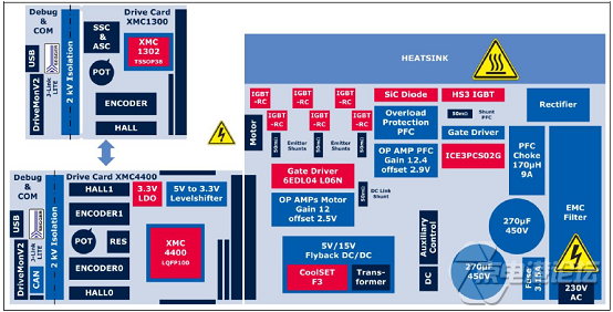
图3.750W三相马达控制板KIT_XMC750WATT_AK_V1框架图
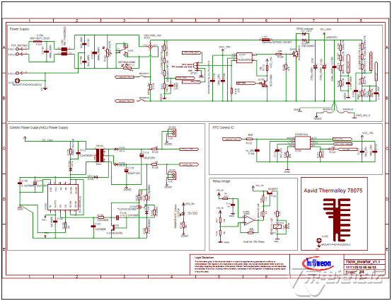
图4.750W三相马达控制板KIT_XMC750WATT_AK_V1电路图(1)

图5.750W三相马达控制板KIT_XMC750WATT_AK_V1电路图(2)
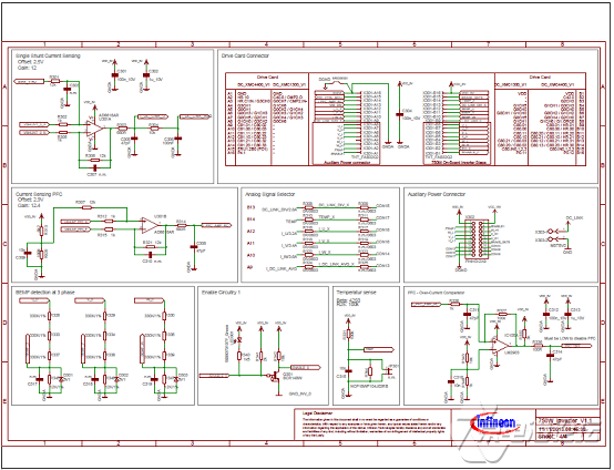
图6.750W三相马达控制板KIT_XMC750WATT_AK_V1电路图(3)
750W三相马达控制板KIT_XMC750WATT_AK_V1质料清单:
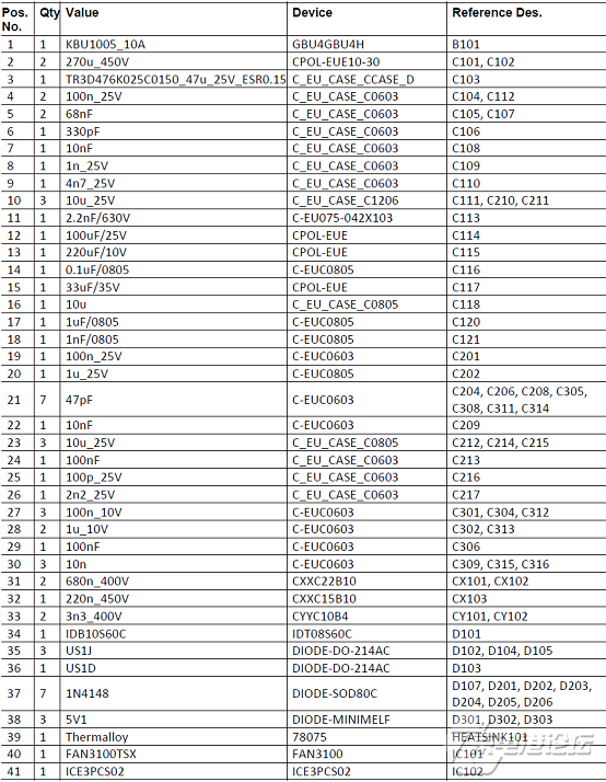
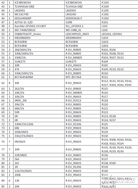
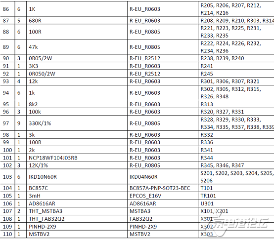
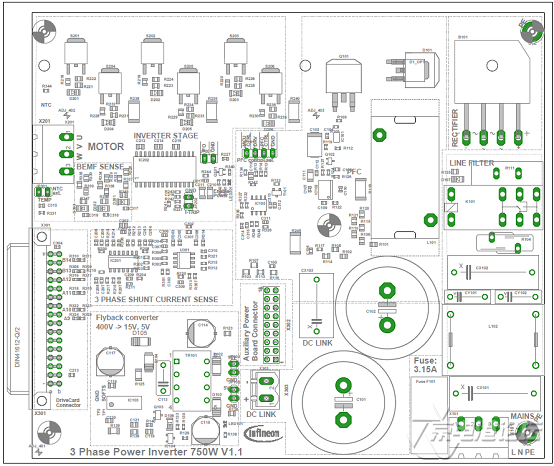
图7.750W三相马达控制板KIT_XMC750WATT_AK_V1 PCB元件结构图
详情请复制打开此衔接地址:
http://www.infineon.com/dgdl/Infineon-XMC4400-DS-v01_01-en.pdf?fileId=db3a30433afc7e3e013b3cfb455565a3
和http://www.infineon.com/dgdl/Board_Users_Manual_3phase_Power_Inverter_750W_R1.0.pdf?fileId=db3a304343e0037c0143fc569bdf0047
 Infineon-XMC4400-DS-v01_01-en.pdf
Board_Users_Manual_3phase_Power_Inverter_750W_R1.0.pdf


 热点图文
热点图文