TI公司的AMIC110是多协议可编工业通信处理器,基于Sitara™ARM Cortex-A8 32位RISC处理器,工作频率高达300MHz,支持高级操作系统(HLOS),集成了NEON™ SIMD协处理器,外设和工业接口,32KB L1指令缓存和32KB数据缓存,256KB L2缓存,176KB引导ROM,64KB专用RAM,64KB通用片上存储器控制器(OCMC) RAM.协议包括EtherCAT, PROFINET IRT, EtherNet/IP, PROFIBUS, Ethernet Powerlink, Sercos III.主要用在工业通信,连接工业驱动器和背板I/OI.本文介绍了AMIC110主要特性,功能框图,以及AMIC110工业通信引擎(ICE)开发平台主要特性,框图,电路图,材料清单和PCB设计图.
The AMIC110 device is a multiprotocol programmable industrial communications processor providingready-to-use solutions for most industrial Ethernet and fieldbus communications slaves, as well as somemasters. The device is based on the ARM Cortex-A8 processor, peripherals, and industrial interfaceoptions. The device supports high-level operating systems (HLOS). Linux® and TI-RTOS are available freeof charge from TI. Other RTOS are also offered by TI ecosystem partners. The AMIC110 microprocessoris an ideal companion communications chip to the C2000 family of microcontrollers for connected drives.
The microprocessor unit (MPU) subsystem is based on the ARM Cortex-A8 processor. The PRU-ICSS isseparate from the ARM core, allowing independent operation and clocking for greater efficiency andflexibility. The PRU-ICSS enables additional peripheral interfaces and real-time protocols such asEtherCAT, PROFINET IRT, EtherNet/IP, PROFIBUS, Ethernet Powerlink, Sercos III, and others.
Additionally, the programmable nature of the PRU-ICSS, along with its access to pins, events and allsystem-on-chip (SoC) resources, provides flexibility in implementing fast, real-time responses, specializeddata handling operations, custom peripheral interfaces, and in offloading tasks from the other processorcores of SoC.
AMIC110主要特性:
• Up to 300-MHz Sitara™ ARM® Cortex®-A8 32‑BitRISC Processor
C NEON™ SIMD Coprocessor
C 32KB of L1 Instruction and 32KB of Data CacheWith Single-Error Detection (Parity)
C 256KB of L2 Cache With Error Correcting Code(ECC)
C 176KB of On-Chip Boot ROM
C 64KB of Dedicated RAM
C Emulation and Debug - JTAG
C Interrupt Controller (up to 128 InterruptRequests)
• On-Chip Memory (Shared L3 RAM)
C 64KB of General-Purpose On-Chip MemoryController (OCMC) RAM
C Accessible to All Masters
C Supports Retention for Fast Wakeup
• External Memory Interfaces (EMIF)
C mDDR(LPDDR), DDR2, DDR3, DDR3LController:
C mDDR: 200-MHz Clock (400-MHz Data Rate)
C DDR2: 266-MHz Clock (532-MHz Data Rate)
C DDR3: 400-MHz Clock (800-MHz Data Rate)
C DDR3L: 400-MHz Clock (800-MHz DataRate)
C 16-Bit Data Bus
C 1GB of Total Addressable Space
C Supports One x16 or Two x8 Memory DeviceConfigurations
C General-Purpose Memory Controller (GPMC)
C Flexible 8-Bit and 16-Bit AsynchronousMemory Interface With up to Seven ChipSelects (NAND, NOR, Muxed-NOR, SRAM)
C Uses BCH Code to Support 4-, 8-, or 16-BitECC
C Uses Hamming Code to Support 1-Bit ECC
C Error Locator Module (ELM)
C Used in Conjunction With the GPMC toLocate Addresses of Data Errors fromSyndrome Polynomials Generated Using aBCH Algorithm
C Supports 4-, 8-, and 16-Bit per 512-ByteBlock Error Location Based on BCHAlgorithms
• Programmable Real-Time Unit Subsystem andIndustrial Communication Subsystem (PRU-ICSS)
C Supports Protocols such as EtherCAT®,PROFIBUS, PROFINET, EtherNet/IP™, andMore
C Two Programmable Real-Time Units (PRUs)
C 32-Bit Load/Store RISC Processor Capableof Running at 200 MHz
C 8KB of Instruction RAM With Single-ErrorDetection (Parity)
C 8KB of Data RAM With Single-Error Detection(Parity)
C Single-Cycle 32-Bit Multiplier With 64-BitAccumulator
C Enhanced GPIO Module Provides Shift-In/Out Support and Parallel Latch on ExternalSignal
C 12KB of Shared RAM With Single-ErrorDetection (Parity)
C Three 120-Byte Register Banks Accessible byEach PRU
C Interrupt Controller (INTC) for Handling SystemInput Events
C Local Interconnect Bus for Connecting Internaland External Masters to the Resources Insidethe PRU-ICSS
C Peripherals Inside the PRU-ICSS:
C One UART Port With Flow Control Pins,Supports up to 12 Mbps
C One Enhanced Capture (eCAP) Module
C Two MII Ethernet Ports that Support IndustrialEthernet, such as EtherCAT
C One MDIO Port
• Power, Reset, and Clock Management (PRCM)Module
C Controls the Entry and Exit of Stand-By andDeep-Sleep Modes
C Responsible for Sleep Sequencing, PowerDomain Switch-Off Sequencing, Wake-Up
Sequencing, and Power Domain Switch-OnSequencing
C Clocks
C Integrated 15- to 35-MHz High-FrequencyOscillator Used to Generate a Reference
Clock for Various System and PeripheralClocks
C Supports Individual Clock Enable and DisableControl for Subsystems and Peripherals toFacilitate Reduced Power Consumption
C Five ADPLLs to Generate System Clocks(MPU Subsystem, DDR Interface, USB and
Peripherals [MMC and SD, UART, SPI, I2C],L3, L4, Ethernet, GFX [SGX530], LCD Pixel
Clock (1))
C Power
C Two Nonswitchable Power Domains (Real-Time Clock [RTC], Wake-Up Logic[WAKEUP])
C Three Switchable Power Domains (MPUSubsystem [MPU], SGX530 [GFX](1),Peripherals and Infrastructure [PER])
C Implements SmartReflex™ Class 2B for CoreVoltage Scaling Based On Die Temperature,
Process Variation, and Performance(Adaptive Voltage Scaling [AVS])
C Dynamic Voltage Frequency Scaling (DVFS)
• Real-Time Clock (RTC)
C Real-Time Date (Day-Month-Year-Day of Week)and Time (Hours-Minutes-Seconds) Information
C Internal 32.768-kHz Oscillator, RTC Logic and1.1-V Internal LDO
C Independent Power-on-Reset(RTC_PWRONRSTn) Input
C Dedicated Input Pin (EXT_WAKEUP) forExternal Wake Events
C Programmable Alarm Can be Used to GenerateInternal Interrupts to the PRCM (for Wakeup) orCortex-A8 (for Event Notification)
C Programmable Alarm Can be Used WithExternal Output (PMIC_POWER_EN) to Enablethe Power Management IC to Restore Non-RTCPower Domains
• Peripherals
C Up to Two USB 2.0 High-Speed OTG PortsWith Integrated PHY
C Up to Two Controller-Area Network (CAN) Ports
C Supports CAN Version 2 Parts A and B
C Up to Two Multichannel Audio Serial Ports(McASPs)
C Transmit and Receive Clocks up to 50 MHz
C Up to Four Serial Data Pins per McASP PortWith Independent TX and RX Clocks
C Supports Time Division Multiplexing (TDM),Inter-IC Sound (I2S), and Similar Formats
C Supports Digital Audio Interface Transmission(SPDIF, IEC60958-1, and AES-3 Formats)
C FIFO Buffers for Transmit and Receive (256Bytes)
C Up to Six UARTs
C All UARTs Support IrDA and CIR Modes
C All UARTs Support RTS and CTS FlowControl
C UART1 Supports Full Modem Control
C Up to Two Master and Slave McSPI SerialInterfaces
C Up to Two Chip Selects
C Up to 48 MHz
C Up to Three MMC, SD, SDIO Ports
C 1-, 4- and 8-Bit MMC, SD, SDIO Modes
C MMCSD0 has Dedicated Power Rail for 1.8‑Vor 3.3-V Operation
C Up to 48-MHz Data Transfer Rate
C Supports Card Detect and Write Protect
C Complies With MMC4.3, SD, SDIO 2.0Specifications
C Up to Three I2C Master and Slave Interfaces
C Standard Mode (up to 100 kHz)
C Fast Mode (up to 400 kHz)
C Up to Four Banks of General-Purpose I/O
(GPIO) Pins
C 32 GPIO Pins per Bank (Multiplexed WithOther Functional Pins)
C GPIO Pins Can be Used as Interrupt Inputs(up to Two Interrupt Inputs per Bank)
C Up to Three External DMA Event Inputs that canAlso be Used as Interrupt Inputs
C Eight 32-Bit General-Purpose Timers
C DMTIMER1 is a 1-ms Timer Used forOperating System (OS) Ticks
C DMTIMER4CDMTIMER7 are Pinned Out
C One Watchdog Timer
C 12-Bit Successive Approximation Register(SAR) ADC
C 200K Samples per Second
C Input can be Selected from any of the EightAnalog Inputs Multiplexed Through an 8:1
Analog Switch
C Up to Three Enhanced High-Resolution PWMModules (eHRPWMs)
C Dedicated 16-Bit Time-Base Counter WithTime and Frequency Controls
C Configurable as Six Single-Ended, Six Dual-Edge Symmetric, or Three Dual-EdgeAsymmetric Outputs
• Device Identification
C Contains Electrical Fuse Farm (FuseFarm) ofWhich Some Bits are Factory Programmable
C Production ID
C Device Part Number (Unique JTAG ID)
C Device Revision (Readable by Host ARM)
• Debug Interface Support
C JTAG and cJTAG for ARM (Cortex-A8 andPRCM), PRU-ICSS Debug
C Supports Device Boundary Scan
C Supports IEEE 1500
• DMA
C On-Chip Enhanced DMA Controller (EDMA) hasThree Third-Party Transfer Controllers (TPTCs)and One Third-Party Channel Controller(TPCC), Which Supports up to 64Programmable Logical Channels and EightQDMA Channels. EDMA is Used for:
C Transfers to and from On-Chip Memories
C Transfers to and from External Storage(EMIF, GPMC, Slave Peripherals)
• Inter-Processor Communication (IPC)
C Integrates Hardware-Based Mailbox for IPC andSpinlock for Process Synchronization BetweenCortex-A8, PRCM, and PRU-ICSS
C Mailbox Registers that Generate Interrupts
C Four Initiators (Cortex-A8, PRCM, PRU0,PRU1)
C Spinlock has 128 Software-Assigned LockRegisters
• Security
C Secure Boot
• Boot Modes
C Boot Mode is Selected Through BootConfiguration Pins Latched on the Rising Edgeof the PWRONRSTn Reset Input Pin
• Package:
C 324-Pin S-PBGA-N324 Package(ZCZ Suffix), 0.80-mm Ball Pitch
AMIC110应用:
• Industrial Communications
• Connected Industrial Drives
• Backplane I/O
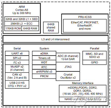
图1. AMIC110功能框图
AMIC110工业通信引擎(ICE)开发平台
The AMIC110 Industrial Communications Engine (ICE) is a development platform targeted at industrial communications and industrial ethernet in particular. Key to the AMIC110 ICE is the Sitara AMIC110 SoC that features ARM® Cortex™-A8 Processor along with the Programmable-Realtime Unit Industrial Communications Sub-System (PRU-ICSS) that enables the integration of real-time industrial protocols, without needing ASIC or FPGA. With a boosterpack form factor, the AMIC110 ICE can be used in conjunction with C2000 Launch pads for developing solutions for Connected Motor Drives, as well as Industrial Sensors and IOs in Factory Automation.
AMIC110工业通信引擎(ICE)开发平台主要特性:
AMIC110 SoC featuring Sitara™ ARM® Cortex®-A8 and PRU-ICSS
512 MByte of DDR3 and 8 MByte of SPI flash
2x 10/100 industrial ethernet connectors with external magnetics
20-pin JTAG header to support all types of external emulator
RoHS and REACH compliant design
EMC-compliant, industrial temp dual port EtherCAT slave with SPI interface
5-V input supply, single chip power management IC TPS650250 to power entire board and dual DP83822 PHYs
3.3V SPI interface to any host processor such as C2000 (for example via launch pads)
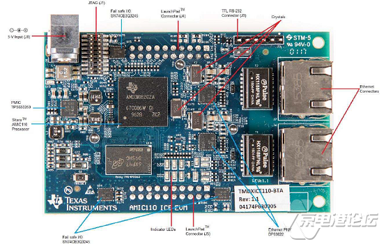
图2. AMIC110工业通信引擎(ICE)外形图(正面)
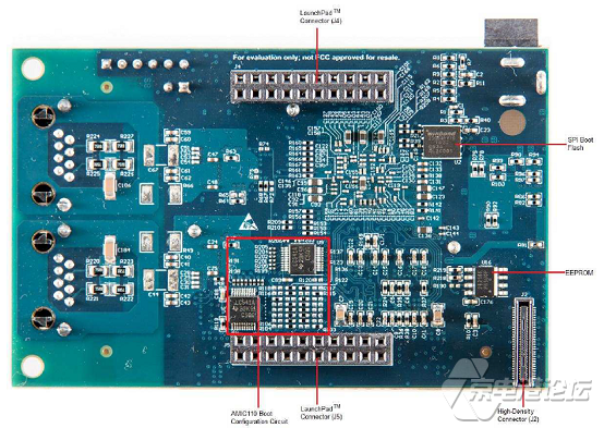
图3. AMIC110工业通信引擎(ICE)外形图(背面)
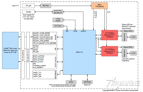
图4. AMIC110工业通信引擎(ICE)功能框图

图5. AMIC110工业通信引擎(ICE)电路图(1)
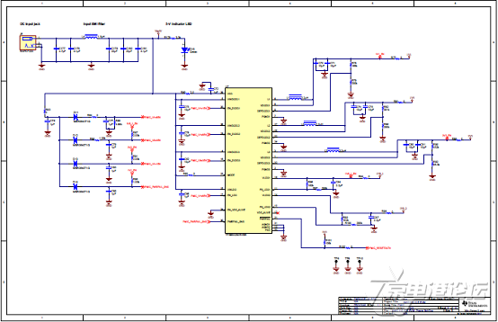
图6. AMIC110工业通信引擎(ICE)电路图(2)
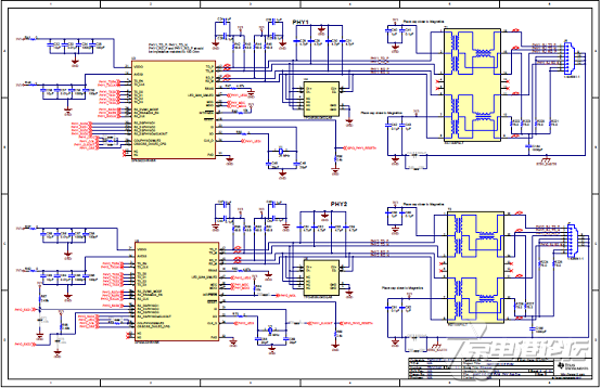
图7. AMIC110工业通信引擎(ICE)电路图(3)

图8. AMIC110工业通信引擎(ICE)电路图(4)

图9. AMIC110工业通信引擎(ICE)电路图(5)
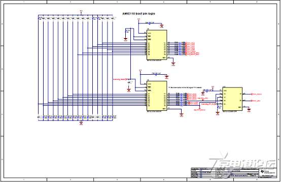
图10. AMIC110工业通信引擎(ICE)电路图(6)
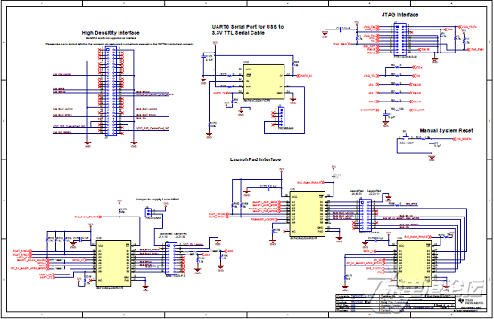
图11. AMIC110工业通信引擎(ICE)电路图(7)
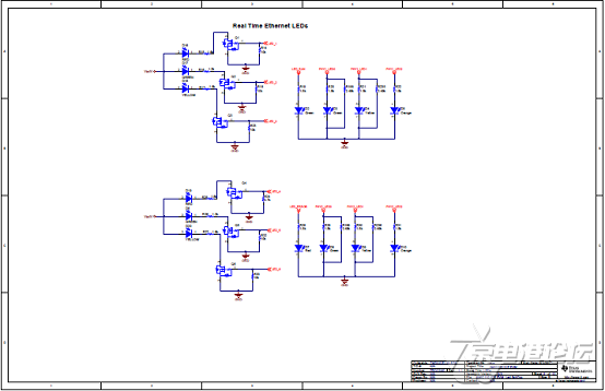
图12. AMIC110工业通信引擎(ICE)电路图(8)
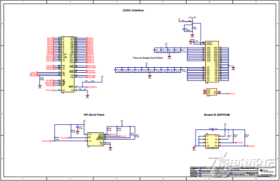
图13. AMIC110工业通信引擎(ICE)电路图(9)
AMIC110工业通信引擎(ICE)材料清单:
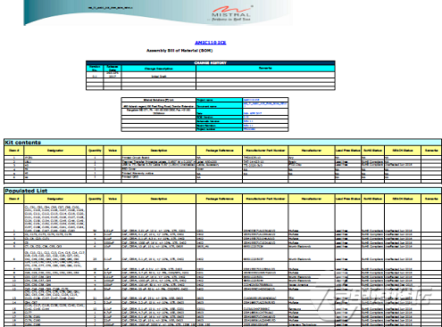

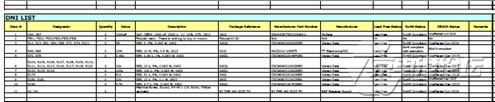

图14. AMIC110工业通信引擎(ICE) PCB设计图(1)

图15. AMIC110工业通信引擎(ICE) PCB设计图(2)
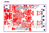
图16. AMIC110工业通信引擎(ICE) PCB设计图(3)
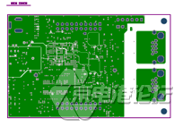
图17. AMIC110工业通信引擎(ICE) PCB设计图(4)
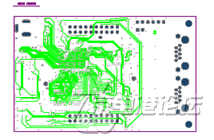
图18. AMIC110工业通信引擎(ICE) PCB设计图(5)
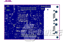
图19. AMIC110工业通信引擎(ICE) PCB设计图(6)
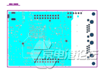
图20. AMIC110工业通信引擎(ICE) PCB设计图(7)
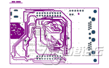
图21. AMIC110工业通信引擎(ICE) PCB设计图(8)
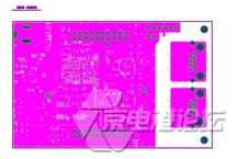
图22. AMIC110工业通信引擎(ICE) PCB设计图(9)
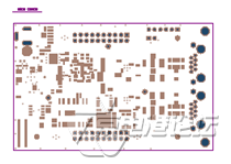
图23. AMIC110工业通信引擎(ICE) PCB设计图(10)
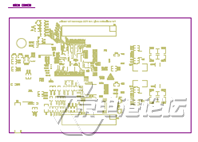
图24. AMIC110工业通信引擎(ICE) PCB设计图(11)
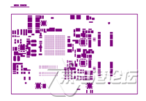
图25. AMIC110工业通信引擎(ICE) PCB设计图(12)

图26. AMIC110工业通信引擎(ICE) PCB设计图(13)
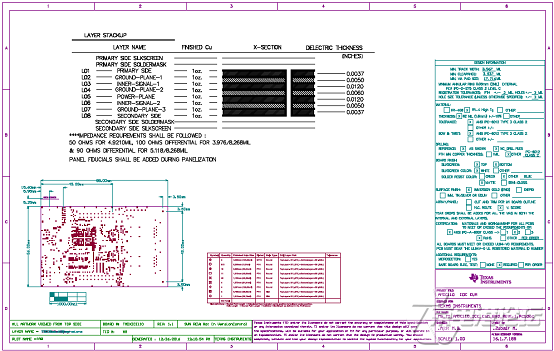
图27. AMIC110工业通信引擎(ICE) PCB设计图(14)
详情请见:
http://www.ti.com/lit/ds/symlink/amic110.pdf
和http://www.ti.com/lit/ug/spruie6/spruie6.pdf
![]()


 热点图文
热点图文